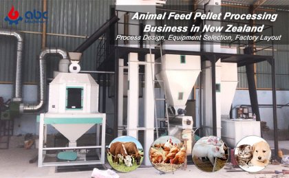
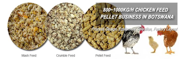
For a poultry feed plant, layout design directly ties to production efficiency—especially when targeting stable output of pellet feed for poultry or chicken feed pellets. Traditional 2D layouts often fail to account for on-site spatial constraints (e.g., column positions, ceiling height) or material flow bottlenecks, leading to rework during construction.

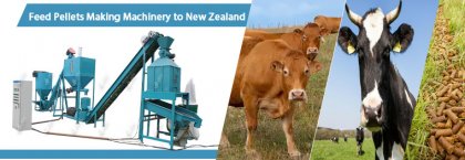
3D Poultry Feed Plant Design
3D layout design addresses this by creating a scalable, interactive model that aligns poultry feed production line equipment with actual site conditions. This article follows industrial layout design best practices, focusing on how 3D tools optimize equipment placement and streamline processes for poultry feed production.

Core Principles of 3D Layout for Poultry Feed Plants
3D layout design for poultry feed plants adheres to three key principles (consistent with industrial pellet plant layout logic):
-
Site Adaptability: 3D models map real-site dimensions first, ensuring equipment like poultry feed grinders or mixers fit within available space (e.g., adjusting silo height for low-ceiling workshops).
-
Logistics Priority: Prioritize shortest-path material transport—critical for preserving the nutritional value of feed for poultry and reducing energy use.
-
Compliance & Safety: 3D visualization pre-reserves space for hygiene channels (required for poultry feed pellets production) and emergency exits, avoiding post-construction modifications.
Key Zones: 3D Layout & Equipment Configuration
A poultry feed plant’s linear workflow (raw material → processing → finished product) determines its zone layout. Below is how 3D design optimizes each key area’s equipment placement:
1. Raw Material Receiving & Storage
This zone handles bulk raw materials (corn, soybean meal) for poultry feed pellets. 3D models first simulate silo placement: aligning silos parallel to the unloading conveyor reduces material transport distance, while 3D load-bearing calculations ensure silos (10-15m tall) match the plant’s foundation capacity. Magnetic separators and automatic conveyors are positioned in 3D to avoid overlapping with silo discharge paths, preventing metal impurities from entering downstream equipment.
2. Crushing Zone
The goal here is to grind raw materials into 0.8-1.2mm particles for feed for poultry. 3D layout positions poultry feed grinders (or specialized chicken feed grinders) 3-4m apart to leave room for maintenance, while aligning grinder discharge ports directly with mixing zone conveyors—this cuts transport time by 30% vs. 2D layouts. Cyclone dust collectors are also integrated in 3D to ensure ductwork doesn’t block access to grinders.
3. Mixing & Pelleting Zones

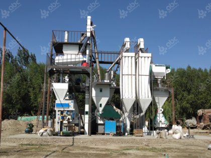
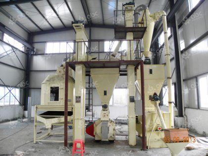
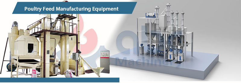
Large Poultry Feed Pellet Plant Show Details
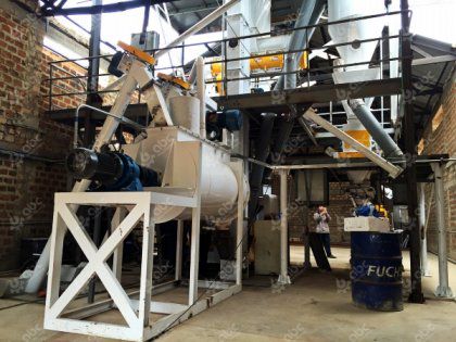
For the mixing zone, 3D models place horizontal ribbon mixers (ideal for poultry feed mixer machine needs) directly below crusher discharges to utilize gravity feeding, eliminating extra conveyors. For regional plants (e.g., using poultry feed mixer machine Kenya specs), 3D scaling adjusts mixer size to match local raw material supply.
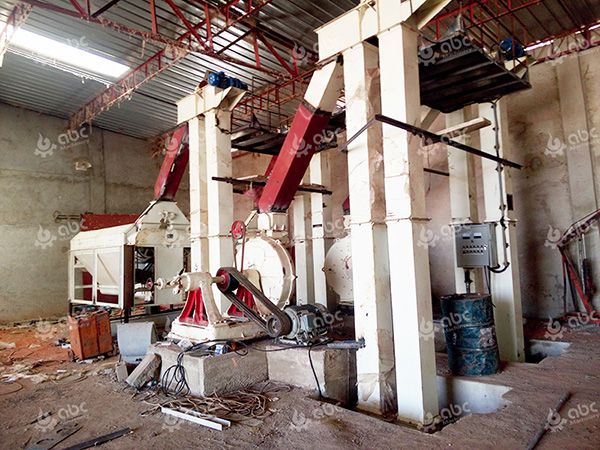
In the pelleting zone, 3D design positions ring die pellet mills (for chicken feed pellets) 2m away from mixers to accommodate steam pipelines—preventing heat damage to mixer components. Vibration simulations in 3D also guide foundation reinforcement for pellet mills, avoiding long-term structural issues.
4. Finished Product Storage & Packaging
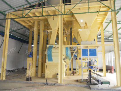
3D layout aligns finished silos with automatic packaging machines (for pellet feed for chickens) to minimize material handling. Palletizers are placed near the 4m-wide loading zone (simulated in 3D to avoid blocking truck access), while level sensors in silos are mapped in 3D to ensure real-time inventory monitoring doesn’t require extra wiring space.
Process Optimization with 3D Simulation
3D layout isn’t just about placement—it streamlines the entire poultry feed production line:
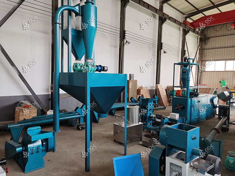
3D Poultry Feed Pellet Production Processing Optimization
-
Material Flow: 3D maps avoid cross-flow paths (e.g., raw material conveyors crossing finished product lines), reducing contamination risks for poultry pellet feed. One plant repositioned its cooling zone via 3D simulation, cutting transport distance by 40% and energy use by 12%.
-
Capacity Matching: 3D models balance equipment output—if a poultry feed grinder processes 2 tons/hour but the mixer only handles 1.5 tons/hour, 3D simulations suggest adding a buffer hopper to prevent bottlenecks.
-
Maintenance Efficiency: 3D “maintenance zones” (1.5m clearance around grinders or mixers) are marked pre-construction, reducing downtime for repairs by 25%.
With years of experience in poultry feed plant design, ABC Machinery has helped global clients build efficient feed production lines. We gain rich expertise in meeting diverse needs, like matching Kenya’s poultry feed mixer specs. Contact us for details on 3D layout, equipment and process optimization.
 Feed Processing Technology